3. Stock, origin and tools#
Two things have to be true before a toolpath means anything: the app has to know what is on your table, and it has to know what is in your spindle. Get these right once at the start of a project and everything downstream — depths, the simulation, the feeds, the warnings at export — follows from them.
Setup: the stock#
Setup is the third tab in the sidebar. It fills the panel and leaves the view visible, so edits show up live.
Dimensions#
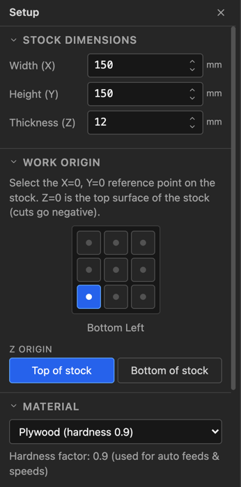
Width (X), Height (Y) and Thickness (Z) are the actual piece of material. Thickness is the one that does real work: a profile cut to 12 mm through 12 mm stock is what separates the part, and the simulation carves a block of exactly this depth.
Work origin#
Two separate questions, and both matter more than they look.
X0 Y0 is the nine-position grid — which corner or edge of the stock the machine's zero corresponds to. Bottom left is the default and is what most hobby machines get jogged to. Pick centre if you locate work from the middle, which is common with a fixture or a rotary axis.
Z0 is where the tool's zero height is:
| Setting | Means | Zero the bit against |
|---|---|---|
| Top of stock (default) | Z0 is the surface; all cuts are negative | The top of the material |
| Bottom of stock | Z0 is the spoilboard; the surface is at +thickness | The table or spoilboard |
Top of stock is the usual choice — you touch off on the workpiece with a piece of paper or a Z-probe and go. Bottom of stock suits work where the material thickness varies but the finished depth from the table must not, such as surfacing a slab.
Whichever you choose, the export review restates it back to you before the file is written. Read that line against how you actually zeroed the machine. Getting this wrong is the fastest way to plunge a cutter through a spoilboard.
Material#
The material is not decoration. Each has a hardness factor that drives the automatic feeds and speeds:
| Softer ← | → Harder | |||
|---|---|---|---|---|
| Cedar 0.5 · Pine 0.6 | HDPE 0.7 · MDF 0.8 · Plywood 0.9 | Walnut 1.1 · Cherry 1.2 | Maple 1.3 · Oak 1.4 | Aluminum 2.5 · Brass 2.8 |
Aluminium and brass additionally carry a maximum surface speed, because the failure mode in metal is not a broken cutter but a bit that overheats and welds swarf to its own edge. If your spindle cannot run slow enough to respect it, the export review says so.
The tool library#
The Tool Library tab across the top holds your cutters. It is saved with the project and kept in the browser between sessions, so a new project starts with the tools you already own.
Folders#
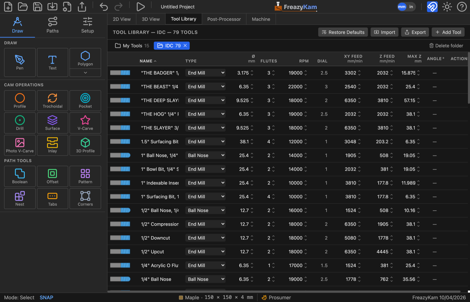
The library is split into folders, shown as tabs above the table. My Tools is your own rack — the cutters you actually own — and is always there. Every other folder is a tool set you imported, and an import always lands in a folder of its own, so a vendor's 80-bit catalogue never mixes in with, renames, or overwrites the tools you set up yourself. The number on each tab is how many tools it holds; click a tab to show its tools.
- Rename a folder by double-clicking its tab.
- Delete a folder with the × on its tab (or Delete folder at the right of the bar). The dialog lists what goes, and keeps any tool the open project cuts with. My Tools can't be deleted.
- Move a tool to another folder with the folder icon in its row's Actions — pick a folder, or New folder… to make one. The tool keeps its identity, so toolpaths that use it are unaffected.
- Copy to My Tools (the copy icon, in an imported folder's rows) adds the bit to your own rack and leaves the folder as the vendor published it. This is how a catalogue bit you've bought becomes one of yours.
Add Tool adds to the folder you're looking at, and Export saves that folder as a
.fkset file to share. (The whole library, every folder, goes out with Setup's
Export — see settings files.)
Importing a tool set#
Import reads two kinds of file:
- a FreazyKam
.fkset— a tool set a friend exported, or one of your own from another computer; - a Fusion 360 tool library (
.json) — the format most bit makers publish their catalogue in. Look on the maker's website for a Fusion 360 download.
A dialog asks which folder the tools go into — the maker's name by default (IDC Woodcraft), or the file's name — and lists what will be added before anything changes. Pick an existing folder to bring a catalogue up to date: tools already there exactly are skipped, and a changed one comes in beside the old as "Name (imported)", so importing the same file twice adds nothing. Your own tools are never touched. Typing My Tools as the folder is the one way to import straight into your rack.
From a Fusion 360 library, FreazyKam takes each bit's type, diameter, flutes, flute length, and the maker's starting RPM, feed and plunge, converted to millimetres. A few things are worth knowing:
- Bits FreazyKam can't model are left out, and listed. Round-over (radius) bits are the usual ones — the dialog names each one and why.
- A bull-nose or bowl bit comes in as a Bull Nose, keeping its corner radius.
- A V-bit's Max Z is worked out from its cone, not copied from the file — catalogues often get the flute length wrong (one lists a ½" 90° V-bit as 1.7 mm deep when its cone is 6.35 mm).
- A taper's angle comes in per side, and its Ø is the tip — the same conventions the library uses (below).
- The maker's feeds are starting numbers for their bit, not for your machine. With Auto Feeds & Speeds on, each cut works out its own anyway.
Restore Defaults puts back the tools FreazyKam comes with in My Tools — imported folders are not touched. It first lists what will be removed, which default tools come back, and which of yours are kept because the open project cuts with them — an operation names its tool, so those stay, or its toolpath would lose its cutter. It can't be undone with Undo, so the dialog offers Export a backup.
The table#
Each row is one cutter. The little picture at the left is drawn from that tool's own numbers, so a taper really does taper and a V-bit really does come to a point — a quick check that a row says what you meant.
| Column | Means |
|---|---|
| Name | Yours to choose. Name them the way you'd reach for them in the shop |
| Type | End Mill, Bull Nose, Ball Nose, V-bit, Taper End Mill, Drill — this decides which operations offer it |
| Ø | Cutting diameter — except on a taper, where it is the tip diameter |
| Flutes | With RPM and feed, this sets chip load |
| RPM | Spindle speed |
| Dial | The router's speed dial setting for that RPM — shown only when Setup names a trim router with a dial (Spindle) |
| XY Feed | Cutting feed |
| Z Feed | Plunge feed — always slower; a cutter plunging is cutting with its worst geometry |
| Max Z | Deepest this tool may cut, i.e. its usable flute length |
| Angle° / R | V-bits: the included angle. Tapers: the angle per side. Bull noses: the corner radius. Hover the field to see which. A dash for everything else |
| Actions | Shown when you hover a row: move to another folder, copy to My Tools (imported folders only), delete |
Type decides where a tool can be used#
| Tool | Offered to |
|---|---|
| End mill | Profile, Pocket, Trochoidal, Surface, Inlay, helical drilling |
| Bull nose | Profile, Pocket, Trochoidal, 3D Profile (finishing and roughing) |
| Ball nose | Profile, Pocket, Trochoidal, 3D Profile |
| V-bit | V-Carve, Photo V-Carve, Inlay walls, Profile |
| Taper end mill | V-Carve, Inlay walls, 3D Profile, Profile |
| Drill | Peck drilling |
If a cutter you expected isn't in an operation's list, it is the wrong type for that operation. Max Z does not hide a tool — ask for more depth than it has and the depth field warns Exceeds tool Max Z, leaving the decision to you.
Bull nose and bowl bits#
A bull nose has a flat bottom whose edge is rounded into the side by a corner radius, R in the Angle° / R column. A bowl bit is a bull nose with a big corner: the 1" IDC bowl bit has a ⅜" corner, so only the middle ¼" of its bottom is flat. Set R to 0 and it cuts like an end mill; set it to half the diameter and it is a ball nose. When you switch a tool to Bull Nose, R starts at a quarter of its diameter.
It is offered wherever a flat-bottomed or round-bottomed cutter is: Profile, Pocket, Trochoidal, and 3D Profile for finishing or roughing. Two things to know:
- In a pocket, keep the stepover under the flat width (Ø − 2 × R). The passes are spaced as if the whole diameter were flat, so a wider step leaves low ridges between them — about 0.2 mm on the bowl bit at a 0.4" step.
- In 3D Profile it is modelled exactly, flat and corner, so it never cuts into the model. It works the model out on a finer grid when the corner is small, which makes a small-cornered bull nose slower to generate than a ball nose of the same size.
The two angle conventions#
This trips people up because the trade itself is inconsistent, and the library follows the trade rather than tidying it up:
- A V-bit's angle is the included angle — the whole opening. A 60° V-bit has 30° on each side of the axis.
- A taper end mill's angle is per side, which is how the bits are sold.
And a taper's diameter column is its tip, not what it cuts. Its widest cut comes from the tip, the angle and Max Z together: a 5°/side taper on a 2 mm tip with 20 mm of taper cuts Ø5.33 mm at full depth, and its included angle is 10°, for comparison against a V-bit.
The practical difference is at the bottom of a cut. A taper's tip is a small ball, so it can enter a groove narrower than itself and leave a round-bottomed cut instead of refusing the job — which is what makes it good for fine lettering and 3D finishing. A V-bit comes to a true point and closes tighter, which is why an inlay still wants one: a taper's rounded foot leaves a hairline gap at the finished face.
Feeds and speeds#
The bottom of the Setup panel decides how hard the machine is driven. Auto Feeds & Speeds is on by default, and it is the right default: it computes a feed, plunge feed, spindle speed and step-down per operation, from the tool, the material and your machine.
Machine rigidity#
The single most useful number here. It scales both how hard the app drives the chip and how deep a pass it takes:
| Level | Suits | |
|---|---|---|
| 🐌 | 1 · Hobby | Light rail or 3D-printed frames, belt drive, small routers |
| 🐢 | 2 · Light hobby | An entry aluminium-extrusion machine |
| 🐇 | 3 · Prosumer | A stiff hobby machine — the default |
| ⚡ | 4 · Heavy | Steel frame, ballscrews, a real spindle |
| 🚀 | 5 · Commercial | Industrial machine |
Set it honestly. Too high and a flexy gantry chatters, deflects and leaves a wandering wall; too low and you spend hours cutting air-light passes. The status bar shows the icon at all times so an over-ambitious setting reads "hot" at a glance.
Spindle#
Set the min and max RPM to what your spindle can actually do — routers bottom out around 10 000. Auto mode picks a speed inside that range.
Then pick your spindle type. If you run a trim router rather than a VFD spindle, this
is worth setting: the app knows the published speed charts for the DeWalt DW6xx /
DWP611 and the Makita RT07 / RT0701C, and translates every RPM into the dial
number you actually turn — dial 2, dial 2.5 — shown in the tool table, the
simulation and the G-code comments. G-code S18000 is no use if your router has no idea
what an S-word is.
Max feed rate#
A hard ceiling, in mm/min. Set it to what your machine can move without losing steps, and the app will not exceed it.
This one has a consequence worth understanding. Chip load is feed ÷ (RPM × flutes), and it does not depend on how deep the pass is. So when the machine cannot feed fast enough to reach a sensible chip load, the correct fix is to slow the spindle down, not to take a shallower cut — and that is what the app does. A bit that is fed too slowly for its speed doesn't cut; it rubs, heats and dulls.
The chip-load gauge#
Whether the numbers are right is answered while the simulation runs, in the readout under the stock:
| Reading | Ratio to target | Means |
|---|---|---|
| 🔴 rubbing · too hot | below 0.75 | Feed too slow for the RPM — the edge rubs instead of cutting |
| 🟢 sweet spot | 0.75 – 1.4 | Where you want to be |
| 🔵 chips too large | above 1.4 | Feed too fast for the RPM — risk of breaking the cutter |
On manual feeds the app also suggests the feed that would put you back in the band. This is the honest check on everything in this chapter: set the stock, set the tools, then watch the gauge on a simulated run before you cut anything.
The model produces sane starting numbers, not shop-certified values. It knows your tool, your material and how stiff you said your machine is; it does not know your cutter is dull, your stock is a knotty board, or your workholding is a bit optimistic. Treat its output the way you'd treat a manufacturer's chart — a place to start.
Your settings in a file#
Setup → Settings File saves everything this browser keeps for you — machine, tool
library, post-processors, last-used form values, the Machine tab's settings and interface
choices — as one .fkset file. Use it to move to another computer or browser, to keep a
backup, or to send along with a problem report.
Import… shows what's in the file, a checkbox per part, before anything changes:
- Tools and post-processors are added to yours by default — each row says how many are already in yours and how many it would add. One with the same name as yours but different contents comes in as a copy, "Name (imported)"; an identical one is skipped. Switch a row to Replace to swap yours for the file's instead — the way to move your own setup to a new browser without ending up with two sets. Tools the open project uses are kept either way.
- Machine, stock defaults, last-used form values (the settings each form opens with — every Generate remembers them), Machine tab and interface replace yours, so they start unticked — tick them when restoring your own backup, leave them when the file came from someone else.
Any replace turns the button red (Import and replace) and offers Export a backup first: settings aren't covered by Undo.
Restore default machine settings… puts the machine limits, feeds & speeds, motion and spindle back to how they came, after listing every setting that changes (Max feed: 4321 → 3000 mm/min). The stock, your tools and your post-processors aren't touched.
A project file (.fkam) is not a settings file: opening a project only ever loads the
drawing and the tools it uses, never someone else's machine settings.
Next#
- 4. Operations — turning geometry into toolpaths
- 5. Profiles and pockets — cut side, tabs, and the five pocket strategies